
Model/Vehicle Specific information for model MSPNP2-NJ8994 Version 1.3:
- 89-94 240SX w/ SR20DET
Please read all documentation before installing your MegaSquirtPNP ECU, and verify you’ve followed all steps before starting your engine for the first time.
Physical Installation
These cars have the ECU behind the right hand kick panel. There’s a bit of trim that helps hold the panel in place below the glove compartment. Unbolt the panel and you are then able to unbolt the ECU. Remove the center bolt in the ECU connector to unplug the connector. Fasten the MSPNP to the sheet metal in the footwell area and plug in the factory ECU harness connector. Note that this connector must be bolted down tightly for the connector to work – often a bit tighter than you can get with a nut driver, so you will need a wrench handle for this. Finger tight is asking for trouble. (Trust us, we’ve made that mistake a couple times in testing when someone was in a hurry.)
You’ll need to hook up the MSPNP’s built in MAP sensor. Cut the vacuum line at the fuel pressure regulator and insert the included tee fitting. Run the vacuum line from this tee through a grommet in the firewall and to the barb on the back of the MSPNP.
We also recommend routing the tuning cable from the ECU to a location on the console of the passenger compartment, somewhere where you can easily tuck it away when not in use.
At this point, it is safe to power the ECU up, but please make sure you load the appropriate startup map for your specific engine before attempting to start the vehicle. Using the wrong startup map may result in a no-start condition, or even engine damage if the engine is driven hard before the correct map is loaded.
Verifying and Adjusting Base Timing
Once the MSPNP is installed, it is mandatory to check timing on all NJ8994 applications. First, put the MSPNP in fixed timing mode by going to Ignition Settings -> Ignition Options/Decoder Wheel (For v1.2 MSPNP2s, go to Basic Setup -> More Ignition Settings). Set Fixed Advance to “Fixed Timing”, set Timing for Fixed Advance to 15 degrees, and click the Burn button.

While you can adjust the timing in the same manner as with a stock ECU by adjusting the cam angle sensor (CAS), the MSPNP gives you another option: adjust the trigger angle with TunerStudio under the spark settings. Increase the trigger angle to retard the spark, or decrease it to advance the spark. Adjust the number until the timing is at 15 degrees.


If you adjust the CAS for adjusting the timing advance, set the tooth #1 angle to 72 degrees in TunerStudio and turn the distributor until the timing is at a steady 10 degrees BTDC, then lock the cam angle sensor back down and check the timing with the light to make sure the distributor didn’t slip. If you run out of adjustment, use the trigger angle setting in TunerStudio to get the correct timing.

The timing marks are on the front of the engine. The timing mark on the crank pulley may be hard to see; a dab of white paint down inside the mark (wipe off the excess) can help here. The 15 degree mark is three marks ahead of the red TDC stripe on the pulley. Once you have adjusted the trigger angle and/or cam angle sensor to get 15 degrees BTDC, turn off the fixed timing mode by changing the Fixed Timing setting to “Use Table.”
Intake Air Temperature Sensors
Nissan omitted the IAT sensor on the SR20DET. We strongly recommend all users add a GM intake air temperature (IAT) sensor. The best location for the IAT sensor is just upstream of the throttle body. The included IAT installs into a 3/8″ NPT threaded bung. If needed, both Stainless Steel (3/8NPT-BungSS) and Aluminum (3/8NPT-Bung_A) bungs are available separately.
Two 12 inch lengths of wire with pre-crimped pins are included to aid with the IAT installation into the option connector. First, insert the crimped end of each wire into pins 10 and 15 of the included DB15 connector for v1.2 mainboard models or pins 20 and 22 on v1.3 mainboard models. The IAT sensor isn’t polarity sensitive, so it doesn’t matter which wire goes to which pin. Then, pass the wire through he firewall and neatly route it to the location of the IAT and cut to length.
Insert the two IAT wires through the back side of the connector and strip about 1/4″ of insulation off each. Tightly crimp each of the small metal pins in place and gently pull each wire individually from the back side of the connector body so that the crimped end slides into the front of the connector. Be careful to align the pin as it will only slide in one way.
After installing the IAT, turn the ignition key on but do not start the engine. Connect to the MSPNP with TunerStudio. Go to the Tools menu and select Calibrate Thermistor Tables, select Air Temperature Sensor, and select GM from the Common Sensor Values drop down box. Leave the bias resistor setting at 2490.0 ohms. Click Write to Controller. This will update the sensor calibration in the MSPNP.
Once you have an IAT sensor in place, you can remove the MAF and replace it with a length of straight pipe for a less restrictive intake.
Note: If you are using the MSPNP with a turbo or supercharger:
The IAT needs to measure the air temperature as it’s entering the engine, not the ambient air temperature in the engine bay. Only by placing the IAT just before the throttle body can an accurate air temperature measurement be taken AFTER the compressor has heated the air and the intercooler has cooled it. Accurate air temperature measurements are needed for proper fueling and ignition advance calculations.
Alternate CAS Trigger Disc Installation
We’ve included a bolt in trigger disc that must be installed into the stock CAS. This trigger disc has a pattern that works better with MS2 and allows more precise timing control. It bolts right into the stock CAS with no cutting or rewiring required.
To install, simply remove the CAS cover by removing the two Phillips head screws that hold it in place. There’s a single Philips head screw that holds the trigger disc and its mounting plate in place. Unscrew this, remove the disc, and put ours in its place and screw it back together. The trigger disc is meant to be installed with the side shown below facing out as you look into the CAS. Note the position of the outer “window” in relation to the center post notch. If the disk is installed upside down, you’ll need to change the trigger angles in TunerStudio at the minimum.

Rear Option Connector
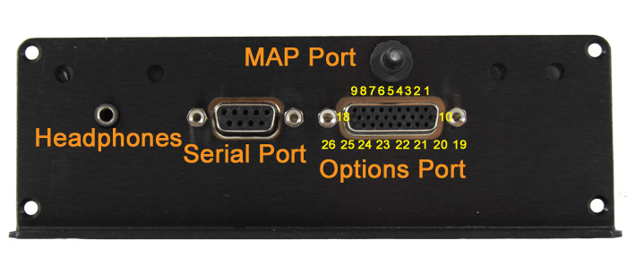
Some of the features on the MSPNP EMS are rather obvious as to why they are there, such as the holes to mount it or the logo on the top to let everyone know how awesome you are due to the EMS you that are running. But it has a few things on it that call for some explanation.
On the back, there is a 26 pin connector. The connector has small numbers cast into it to identify which pin is which. ALL OF THESE CONNECTIONS ARE OPTIONAL AND NOT REQUIRED TO RUN YOUR CAR ON THE MSPNP! These are there keeping the DIY spirit alive, giving you the power to add new capabilities to your vehicle!
- Cam Sensor Input
- Table Switch Input
- Clutch Switch
- Tach Output
- Chassis Ground
- Switched 12V (0.5A Max)
- Boost Control Solenoid
- Injector A Output
- Injector B Output
- Knock Sensor Input
- CanBus High
- CanBus Low
- Launch Control Input
- Spark D Output
- Spark C Output
- Spark B Output
- Spark A Output
- Injector C Output
- External MAP Sensor Input
- IAT Sensor Input
- Oxygen Sensor Input
- Signal Ground
- 5V Vref
- Output 1 Relay Control (ALED)
- Output 2 Relay Control (WLED)
- Injector D Output
The 9 pin connector is a serial port for connecting the MSPNP2 to your laptop with the provided tuning cable. If your laptop does not have the matching plug, you will need a USB to serial adapter, we recommend the USB-2920 that we sell at DIYAutoTune.com for best results.
The small connector that looks like it could be for a set of headphones – well, it is. On engines equipped with a knock sensor, this allows you to listen to the knock sensor. In most cases if your vehicle had a factory knock sensor, we’ve already tied it in through the factory wiring harness. If your vehicle did NOT have a factory knock sensor, you can add one, if you like, using the option connector outlined above.
Some knock sensors have built in filters, and there’s a similar filter in the MSPNP2, so it will cut out a portion of the sounds that are not related to engine knock. You will need to take the cover off to adjust the volume (see section 4, Tuning) as well as adjust the knock sensor; we recommend starting at the lowest setting, fully counterclockwise.
There is a small barbed fitting on the back of the MSPNP’s case. This is for connecting the MAP sensor. The sensor is designed to work with a rubber hose with around 7/64″ – 1/8″ inside diameter, which is included in the kit.
The four screws on the back that look like they might be for adjusting something – they’re not. Leave them alone.
There are four small holes in the side of the case for viewing indicator LEDs. Looking at the side of the case, from left to right, this what these LEDs do:
- 12V Power: This light comes on when the ECU has power.
- Logic Power (5VDC): Normally, this light comes on whenever the 12V Power is ON. Used mostly for specialized diagnostics.
- Tach Pulse: Blinks when you have an RPM signal.
- Knock: Blinks when knock is detected. The more it blinks, the higher the knock level.
