
Model/Vehicle specific installation guide for model MSPNP2-MM9900 Version 2.0:
- 1999-2000 Mazda Miata - Manual Transmission
Please read all documentation before installing your MegaSquirtPNP ECU and verify that you’ve followed all steps before starting your engine for the first time.
Physical Installation
All you’ll need for a successful installation are some basic hand tools. No cutting or drilling of the original sheet metal or bracketry is required.
For a thorough and professional installation, you will need the following items:
-
10mm socket and ratchet
-
Zip Ties
-
Timing Light
-
Laptop with TunerStudio installed
The stock ECU is located under the driver’s side dash board next to the steering column and is secured by two bolts. The lower bolt is readily and visually accessible. The upper bolt is on top of the ECU case and a bit more difficult to reach. Remove these bolts and the ECU will drop down. After the ECU is released from the mount, the three connectors will become more accessible and can be unplugged. These connectors can be difficult to release as they’re a fairly tight fit in the ECU socket as well as being located in a tight location, so be patient during their removal. Press the locking clips and pull on the connector to unseat them from the socket. Slightly rocking the connector back and forth helps with removal. Be cautious and apply as little pulling force on the wiring as possible.


Before installing the MSPNP, you must first run a vacuum line from the engine, through the firewall, and to where the MSPNP will reside. A nipple on top of the intake manifold provides the perfect source for a vacuum reference. Connect one end of the vacuum line here and route it neatly through the engine bay and secure it with zip ties to prevent movement and entanglement.

There is a large rubber grommet in the firewall on the driver’s side corner of the engine bay. CAREFULLY make a slit or hole large enough to pass the vacuum line through. If you use a knife, use extreme caution as there are many wires in this area that you certainly don’t want to damage.

Once the vacuum line is routed to the proper location under the dashboard, connect it to the nipple on the MSPNP. Also, connect the three harness plugs to the MSPNP as well.
To mount the MSPNP, first remove the lower bracket from the OE ECU. The MSPNP fits well in the stock ECU location between the brake and clutch pedals. Reuse the lower bracket only from the original ECU and secure the MSPNP with zip ties to the lower ECU bracket at the bottom of the unit. At the top of the MSPNP, use zip ties to hold it steady against the clutch pedal bracket.


Verifying and Adjusting Base Timing
Because the factory ECU is no longer in control of ignition timing, it will be necessary to make checks to ensure the MSPNP is accurately delivering the proper timing. Improper ignition advance can cause engine damage if improperly set or is left unchecked.
The MSPNP will have a base ignition map loaded and ready to use. However, it is necessary to ensure that the timing advance being commanded by the MegaSquirt is in sync with what the engine is actually receiving. These steps will require the use of a timing light and a laptop with a copy of TunerStudio running.
-
Connect a timing light on the cylinder #1 spark plug wire. Use all due caution here, as secondary ignition voltage can be as high as 100,000 volts or more. Also ensure that the timing light’s cords can not get tangled in moving engine parts or burned on hot components.
- Make sure your tuning laptop is connected to your MSPNP and start your vehicle. If you have not already done so, start TunerStudio MS or TunerStudio Lite. Make sure that your laptop connects to the MSPNP and you are online.
- Navigate to the Ignition Settings -> Ignition Options/Decoder Wheel (For v1.2 MSPNP2s, go to Basic Setup -> More Ignition Settings). If “Fixed Advance” is set to “Use Table”, set it to “Fixed timing”. This will tell the MSPNP to ignore the ignition table and hold a fixed advance angle. Set this value to 10.0 degrees. Burn these changes and close this menu. (Ignore the sections not highlighted in blue rectangles.)

-
Use a timing light to confirm that you have 10 degrees of timing at the crank pulley — the yellow mark will align with “10” on the indicator dial and the white mark will align with “T”. If you have more timing, decrease the “Trigger Angle” value under the Ignition Settings -> Ignition Options/Decoder Wheel (For v1.2 MSPNP2s, go to Basic Setup -> More Ignition Settings) dialog box. If you have less, increase this value.

- Close the “Ignition Options” dialog and go back to the “More Ignition Settings” menu under the “Basic Setup” tab. Set “Fixed Advance” back to “Use Table”. Burn and close this menu. Cycle power to the MSPNP (turn the car off and back on). The MSPNP is now commanding timing advance based on the ignition table.
Removing the Mass Air Flow Meter
Since the MSPNP calculates engine load using a MAP sensor, the air flow meter is no longer needed. While not necessary, it is recommended to remove the AFM for a small performance increase. At the very least, the air meter should be unplugged and the connector neatly tied away.
Auxiliary Outputs

Optional Configurations
Several jumpers are located on the lower, black circuit board inside the MSPNP. These are accessible by removing the top cover and are indicated as depicted below:

Default settings indicated in red
J1: Fuel Pump Selection
On European cars with a factory immobilizer, move the jumper to connect “Fuel Pump” and “Europe w/ immob.” Otherwise, leave the jumper connected to “USA.”
J2: Clutch Switch Connection
Remove this jumper if using the optional center connector to connect a user supplied clutch switch circuit. Otherwise, the OE clutch switch will be directly connected internally.

J3: Oxygen Sensor Selection
Place a jumper between “O2 Select” and “Front” to connect the front OE O2 sensor the the MSPNP. Likewise, connect the jumper between “O2 Select” and “Rear” to connect the front OE O2 sensor.
Rear Option Connector
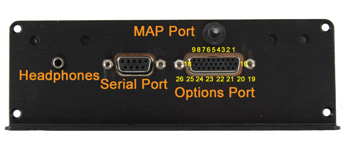
Some of the features on the MSPNP EMS are rather obvious as to why they are there, such as the holes to mount it or the logo on the top to let everyone know how awesome you are due to the EMS you that are running. But it has a few things on it that call for some explanation.
On the back, there is a 26 pin connector. The connector has small numbers cast into it to identify which pin is which. ALL OF THESE CONNECTIONS ARE OPTIONAL AND NOT REQUIRED TO RUN YOUR CAR ON THE MSPNP! These are there keeping the DIY spirit alive, giving you the power to add new capabilities to your vehicle!
- Cam Sensor Input
- Table Switch Input
- Clutch Switch
- Tach Output
- Chassis Ground
- Switched 12V (0.5A Max)
- Boost Control Solenoid
- Injector A Output
- Injector B Output
- Knock Sensor Input
- CanBus High
- CanBus Low
- Launch Control Input
- Spark D Output
- Spark C Output
- Spark B Output
- Spark A Output
- Injector C Output
- External MAP Sensor Input
- IAT Sensor Input
- Oxygen Sensor Input
- Signal Ground
- 5V Vref
- Output 1 Relay Control (ALED)
- Output 2 Relay Control (WLED)
- Injector D Output
The 9 pin connector is a serial port for connecting the MSPNP2 to your laptop with the provided tuning cable. If your laptop does not have the matching plug, you will need a USB to serial adapter, we recommend the USB-2920 that we sell at DIYAutoTune.com for best results.
The small connector that looks like it could be for a set of headphones – well, it is. On engines equipped with a knock sensor, this allows you to listen to the knock sensor. In most cases if your vehicle had a factory knock sensor, we’ve already tied it in through the factory wiring harness. If your vehicle did NOT have a factory knock sensor, you can add one, if you like, using the option connector outlined above.
Some knock sensors have built in filters, and there’s a similar filter in the MSPNP2, so it will cut out a portion of the sounds that are not related to engine knock. You will need to take the cover off to adjust the volume (see section 4, Tuning) as well as adjust the knock sensor; we recommend starting at the lowest setting, fully counterclockwise.
There is a small barbed fitting on the back of the MSPNP’s case. This is for connecting the MAP sensor. The sensor is designed to work with a rubber hose with around 7/64″ – 1/8″ inside diameter, which is included in the kit.
The four screws on the back that look like they might be for adjusting something – they’re not. Leave them alone.
There are four small holes in the side of the case for viewing indicator LEDs. Looking at the side of the case, from left to right, this what these LEDs do:
- 12V Power: This light comes on when the ECU has power.
- Logic Power (5VDC): Normally, this light comes on whenever the 12V Power is ON. Used mostly for specialized diagnostics.
- Tach Pulse: Blinks when you have an RPM signal.
- Knock: Blinks when knock is detected. The more it blinks, the higher the knock level.
